- Mobile: +91 9845484767
- E-Mail: mail@tmisystems.in

CONTROLLER BOARDS
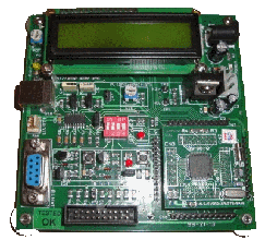
ALS-PJT-89C51ED2 PROJECT BOARD

FEATURES OF ATMEL AT89C51ED2
- On-chip - 64KB flash Program memory.
- 1792 bytes Expanded RAM (XRAM).
- 2048 bytes EEROM.
- SPI interface.
- 16-bit Programmable Counter Array for Compare, Capture, PWM.
- Three programmable Timer/Counters.
- Two External Interrupts.
- Operating Frequency – 11.0592 MHz.
- RS232 compatible serial interface for communication and ISP
- Alphanumeric 16x2 LCD display wit back lighting
- Two nos of general purpose LED’s.
- Two-no.of general purpose push button Switches.
- A Push button switch for Reset and a Slide switch to select either program mode or run mode.
- Four no. of 8-pin single row Berg Sticks connected to PORT 0 to PORT 3.
- Power Adaptor (5V, 1A.)
- Evaluation version of ‘C’ compiler.
- Demo programs for LCD, USART, LED switches.
- 16 nos Flying leads with female bergs for extending IO lines
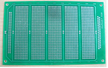
SPECIFICATION FOR PROJECT PROTO BOARD
- Two sided solder masked FR4 PCB with plated through holes @ 2.54mm pitch
- Supply and ground tracks for ease of connection
- Berg pins for connection to project boards using flying leads
- Size 11 x 23 cms
ALS-PJT-ARM2148 ARM PROJECT BOARD

SPECIFICATIONS
- LPC2148 16/32 BIT ARM7TDMI-S with 512K bytes Program Flash, 42K bytes RAM.
- 12MHz Crystal allows easy communication setup.
- One on board voltage regulator for generating 3.3V from +5V input through power adapter.
- One Serial MAX3232 interface with 9 pin DSUB connector for UART0; this is used by the Boot loader program, to program LPC2148 Flash memory without external programmer.
- PIGGY BACK Module carrying LPC2148 Controller.
- Internal ADC circuit-one preset provided for study.
- LCD 16 x 2 alphanumeric display.
- One general purpose led.
- Reset switch for resetting the controller.
- UART1 provision is provided through 3 pin reliamate.
- USB 2.0 Full speed connector, USB link LED.
- Four 12 pin male berg stick for interfacing with any interface board.
- 16 no’s of flying leads for connecting interface board with project board
- Standard JTAG connector with ARM 2x10 pin layout for programming/debugging with ARM-JTAG.
ALS-PJTBRD-ARMCTXM3-01 ARM CORTEX M3 PROJECT BOARD
SPECIFICATIONS
- LPC1768 is an ARM Cortex M3 based micro-controller for embedded applications requiring a high level of integration and low power dissipation
- LPC1768 is a 32/16 bit controller with 512 bytes program flash and 64K bytes of RAM
- 12M Hz crystal allows easy communication setup
- On board voltage regulator for generating 3.3V from +5V input through power adapter
- One serial MAX3232 interface with 9 pin DSUB connector for UART0 which is used by the boot loader program, to program LPC178 flash memory without external programmer
- PIGGY BACK Module carrying LPC1768 Controller
- Onchip ADC – one preset provided for study
- LCD 16×2 alphanumeric display
- One general purpose LED
- Reset switch for resetting the controller
- UART2 provision through 3 pin reliamate
- USB 2.0 device full speed type B connector provided with USB link LED
- Four 20 pin male berg sticks for extending controller signals to any interface board
- 16 no's of flying leads for connecting interface board with project board
- Standard JTAG connector with ARM 2×10 pin layout for programming/ debugging with ARM-JTAG
- 20 pin Standard Trace Port for tracing CPU instruction execution
- A number of software examples in 'C-language' to illustrate the functioning of the interfaces. The software examples are compiled using an evaluation version of KEIL4 'C' compiler for ARM
- 5V ,1A DC adapter and RS232 cable are included
SPECIFICATION FOR PROJECT PROTO BOARD
- Two sided solder masked FR4 PCB with plated through holes @ 2.54mm pitch
- Supply and ground tracks for ease of connection
- Berg pins for connection to project boards using flying leads
- Size 11 x 23 cms
ALS-PJT-PROTO-01 PROTO BOARD

SPECIFICATIONS
- Two sided solder masked FR4 PCB with plated through holes at 2.54mm pitch
- Supply and ground tracks for ease of connection
- Berg pins for connection to project boards using flying leads
- Size 11 x 23 cms